3.1 Test environment
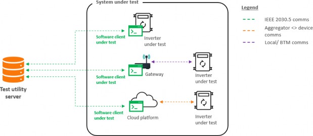
SA Power Networks will make available a test server to support development, integration and execution of this test procedure. It will have a normal state operation for development purposes and will incorporate test cases for each of the tests contained in this procedure for self-service execution. An example of the test environment for testing a communications software client and compatible inverter series is shown below.
Figure 2 – Example Test Environment for Communications Software Client Test Procedure
For an OEM or TP who wishes to test additional inverter series against an already certified communications software client (e.g. aggregator or gateway client) will need to include the certified software client in the test setup as shown below. For execution of the test procedure, the gateway model is classified as a Direct Client, not an Aggregator.
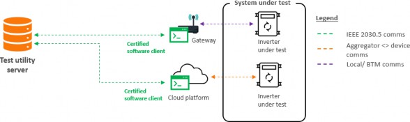
Figure 3 – Example Test Environment for Export Limitation Test Procedure
IEEE 2030.5 test certificates and test server access details will be provided on request to SA Power Networks.
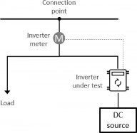
Any execution of these test procedures will require an electrical test setup as shown in the diagram and table below:
Component | Additional requirement |
Inverter | Configured to receive commands from a communications software client (native, gateway or cloud) |
Inverter meter | Measures or enables calculation of net export |
DC source | PV panels or DC Supply of at least 2kW DC during test execution. (Inverters less than 2kW in capacity will be handled individually) |
Load | At least 500W of switchable load |
Figure 4 – Example Electrical Test Setup
The party undertaking the test is responsible for ensuring such a test setup is available during test execution.
3.2 Test Execution
The test server will be always online to enable OEM and TP development, integration and testing.
Formal execution of the communications software client test procedure can be performed anytime against the test server by initiating the automated procedure through the provided user interface. The server will validate expected behaviors against responses and measurements received by the server. Successful completion of the test will create a record that will be reviewed by SA Power Networks before certification is granted.
Completion of the export limit test procedure for the inverter will require witnessing of specific tests by SA Power Networks to assess the physical device response meets stated functional outcomes.
SA Power Networks will provide more information on this process when an OEM or TP is onboarded for testing.
3.3 Test Configuration
In addition to adherence to standard IEEE 2030.5 communications, the following requirements apply to all test procedures:
• Payloads are communicated in XML via HTTPS
o XML version 1.0 with UTF-8 encoding
• Resources contain links to their subordinate resources
• Aggregator clients will need to support REST paging techniques to process lists from the Server that may be incomplete
• Resources use the standard IEEE 2030.5 namespace of: http://ieee.org/2030.5
o CSIP-AUS extensions use namespace of: http://csipaus.org/ns
To support Dynamic Exports, the below functions from CSIP-AUS and IEEE 2030.5:2018 are required to be supported in addition to any other common functionality required to support the following:
• DeviceCapability
• Time
• EndDevice
• FunctionSetAssignments
• DER
o DERList
o DERSettings
o DERStatus
o DERCapability
o DERProgram
o DERControlList
o DefaultDERControl
o Randomisation
o Scheduling
• Response
o DERControlResponse
• Metering Mirror
o MirrorUsagePoint
o MirrorMeterReadingList
o MirrorMeterReading
o MirrorReadingSet
o Reading
• Subscription/Notification
• ConnectionPoint Extension
Resource | Type | Value (secs) |
DeviceCapability | Poll | 300 |
EndDeviceList | Poll | 300 |
FunctionSetAssignmentsList | Poll | 300 |
DERProgramList | Poll | 60 |
DERList • DERStatus • DERSettings • DERCapability | Poll | 60 |
MirrorUsagePoint | Post | 60 |
Resource | Type | Value (secs) |
DeviceCapability | Poll | 300 |
EndDeviceList | Poll | 300 |
FunctionSetAssignmentsList | Poll | 300 |
DERProgramList | Poll | 60 |
DERList • DERStatus • DERSettings • DERCapability | Poll | 60 |
MirrorUsagePoint | Post | 60 |
Resource | Type | Value (secs) |
DeviceCapability | Poll | 300 |
EndDeviceList | Poll | 300 |
FunctionSetAssignmentsList | Poll | 300 |
DERProgramList | Poll | 60 |
DERList • DERStatus • DERSettings • DERCapability | Poll | 60 |
MirrorUsagePoint | Post | 60 |
Upon initial discovery, the Utility Server will configure the following poll and post rates for resources: Please note these values are for testing purposes and do not reflect steady state operations.
The below diagrams highlight the core client-initiated interactions that support the above functions, using a polled client as an example. XML payload examples can be found in the resource files of the IEEE 2030.5 Model download. Examples for CSIP-AUS extensions are found in CSIP-AUS.
Figure 5 shows core client-initiated interactions to support the discovery process.

Figure 5 – Client Interactions (Discovery)
Figure 6 show core client-initiated interactions to support the ongoing operations.
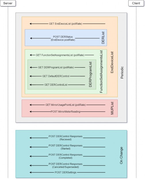
Figure 6 – Client Interactions (Ongoing)